First-Hand:The Anti-Submarine Warfare Ship Command and Control System - The First Spin Off from the Naval Tactical Data System
Introduction
By Capt. Carl C. Drenkard, USN Retired
I have written the attached short history of the ASW Ship Command and Control System development from my perspective as the Bureau of Ships Project Officer and Technical Director from 1964 through 1967. I brought the following relevant experiences and educational background to the job.
US Naval Academy class of 1954, BS, Surface Line Designation US Navy Post Grad School 1959-62, MSEE (major, Underwater Acoustics) ASW Deck Officers Course - Key West Schools Command 1958 Engr Duty Officer (transferred from Surface Line Designation 1961)
Fleet ship assignments:
1. Heavy Cruiser - Division Officer (Gunnery Department), Qualified Officer of the Deck Underway. Operating primarily in Mediterranean
2. Destroyer DD 706 - Gunnery Department Officer, ASW Officer, Senior Watch Officer, Surface Warfare Qualified - including two years of intensive ASW operations across the Western Hemisphere
Assistant BuShips Technical Representative, Saint Paul MN - 1962-63 Mgr. exploratory development programs related to tactical data systems Rank during the program execution was Lieutenant Commander
History of ASWC&CS Development and Early Deployment
Background
The genesis of the Naval Tactical Data System lay in the inability of post World War II shipboard radar plotting teams to keep up with a rapidly changing air situation caused by the advent of high speed jet airplanes, and the highest priority of initial NTDS development was to provide automated aid to anti-air warfare (AAW) battle management. It was apparent from the beginning that NTDS concepts and equipment could be applied to anti-submarine warfare, but it was a case of not stretching project resources too thin. It was also planned that, in time, NTDS would have automated interfaces with anti sub weapons, sonar, electronic warfare sensors and jammers, precise navigation systems, and intelligence handling systems, but these new capabilities had to be engineered one at a time to avoid swamping the available financial and personnel resources. The situation was also made more complex by the fact that every class of NTDS ship had to be uniquely tailored to its mission.
In 1964 anti-submarine warfare got an impetus to be the next focus of NTDS when the new position of Chief of Anti-Submarine Warfare (OP-95) was set up in the Office of the Chief of Naval Operations (OPNAV). Vice Admiral Charles B. Martell was assigned as head of the new office. Martell was already aware of the NTDS project, and one of his first thoughts was a shipboard NTDS-like automated system specialized to manage ASW. He set his staff to work writing up what is called a Specific Operational Requirement (SOR) for a shipboard Anti-Submarine Warfare Ship Command and Control System (ASWSC&CS) to be based on NTDS equipment modified and extended as necessary to support ASW battle management. Vadm. Martell signed out the SOR in September 1964, and he became the OPNAV sponsor for the new development. Commander Chandler E. Swallow, who had been in the original OPNAV NTDS sponsor office had just returned to OPNAV after tours, first as commanding officer of the radar picket destroyer escort USS Kretchmer on the at-sea Distant Early Warning (DEW) Line, and then a tour with the Operational Test and Evaluation Force where he was in charge of at-sea testing of the service test Naval Tactical Data System, followed by a two year tour as Commanding Officer of a missile destroyer USS Towers (DDG-9). Swallow was then assigned to OPNAV’s Office of Research, Development, Test, and Evaluation, and because of his grounding in NTDS, he was assigned as a cosponsor of the ASWSC&CS project.
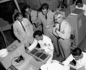
ASWSC&CS was to be a research and development project to evaluate use of NTDS concepts and equipment in ASW, and three ships would be equipped with the R&D system. These would be two 4000 ton destroyer escorts that had anti-submarine warfare as a primary mission and one ASW aircraft carrier. To evaluate the new system, the three ships would operate together in what was called a submarine ‘hunter-killer’ (HUK) group. If the project was successful, ASWSC&CS would not be an end in itself, but would rather form the basis of automation support to ASW battle management in later ship classes that have ASW as their primary mission.
In February 1964 Univac had just completed the prototype of an upgrade of the NTDS CP-642A computer which the Navy designated CP-642B. The B version had twice the processing speed (half the memory access time) of the 642A, meaning it could execute about 200 thousand instructions per second, but it retained the 32,768 30-bit magnetic core memory words of the A version. The OPNAV specific operational requirement did not give the Naval Material Command the luxury of analyzing ASWSC&CS functions to come up with how much processing power the systems in each ship type would need but flatly specified the small ship version would have only one CP-642B and the ASW carrier would get two. It also specified that the system on the DEs would have only four NTDS operator consoles.
However the SOR did say that the system would have electronic inputs not only from the ship’s AN/SPS-10 and AN/SPS-40 (surface and air search radars), but also from the ship’s sonar and an automatic interface with the ship’s analog Mark 114 underwater battery fire control computer. This computer controlled antisubmarine rocket and torpedo deployment against submarines. On the destroyer escorts, the SOR required that single computer was to hold up to 100 tracks from sonar, radars, and the tactical data link (Link-11) combined. Furthermore, in addition to the new ASW functions, the single computer was required to provide the standard NTDS air defense functions of aircraft threat evaluation and weapons assignment and air interceptor control. It was not going to be an easy project; computer memory loading was going to be in the forefront at all times. I had to set some technical principles to guide the system design and accommodate the hardware limitations. More on that later.
The ASW Project Office in the Naval Material Command (CNM) was in charge of the ASWSC&CS project and Engineering Duty Officer Commander Stanford R. Wilde, who had been in charge of installing NTDS in the nuclear cruiser Long Beach at Philadelphia Naval Shipyard in 1962 was assigned as the CNM Project Officer. His major functions were to coordinate interfacing projects in the Material Command and “keep our kitty solvent.” At the same time, in the Bureau of Ships, I was designated the BUSHIPS Project Manager and Technical Director responsible for directing the development, contractors, shore facilities, ship installations, computer software development, interpretation of operational requirements, logistics support, etc.
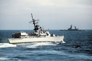
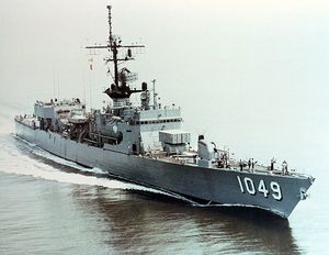
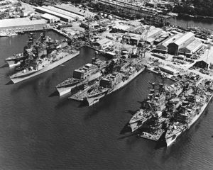
OPNAV checked the construction schedules of new destroyer escorts and found two that seemed to match the ASWSC&CS development schedule. These were the Voge (DE 1047) and Koelsch (DE 1049), of the ten-ship Garcia class of destroyer escorts. Both were under construction at Defoe Shipbuilding Co. at Bay
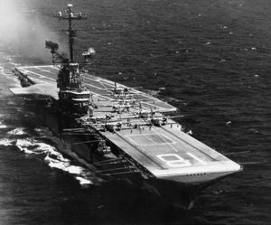
City, Michigan. Voge was scheduled to deliver in late 1966, and Koelch in early 67. Following delivery to the Navy, both ships would be fitted out at Boston Naval Shipyard, and the yard would also install the ASWSC&CS equipment. The installation included extensive changes to the radio communications system a “rip-out” and extensive rearrangement of the Combat Information Center (CIC) and the addition of a large equipment compartment aft of the bridge. We called it the “dog house.” The World War II veteran attack carrier USS Wasp, that had been redesignated in November 1956 as an anti-submarine warfare carrier, was selected as the ASWSC&CS test carrier. She would get the ASWSC&CS equipment installed in her combat information center spaces during an April 1967 regular overhaul at the Boston Naval Shipyard.
The ASW Challenge and the Performance Design
Cdr. Wilde and I examined the operational requirements document and started making a list of functions real time computer processing could do for surface ASW. Our first cut found that there were far more functions required in the destroyer escort variant than could be processed in a single CP 642B computer and four NTDS operator display consoles. Some major decisions had to be made to fashion a system performance design and philosophy that could be executed in the prescribed processing subsystem. I assumed I could control the computer loading through careful control and baselining of the top level “test-to” software performance specifications. That is actually what we did although I had to live with certain starting features of the system, e.g. the number of display consoles. I was able to control the latter through various hardware design initiatives for which we had money.
Here is where my experience in destroyer ASW came into play. I had a clear vision or what we needed in the system and was unafraid to make the hard decisions on its design and character.
It was my sense that a typical destroyer crew knew the fundamentals of ASW and the dictates of such operational manuals as ATP-1 (Allied Tactical Manual #1). I felt that we should not waste our scarce processing resources automating a wide variety of support functions that would not directly support the basic mission of finding, evaluating, engaging, and destroying submarines.
The most fundamental weakness of ASW ships was accurate and responsive track management. This was caused by the submarine’s ability to “garble” the tracking picture by hiding its position under acoustic layers, between convergent zones, behind bubble masks and rudder turn “knuckles“. I decided that our major effort would be directed to challenging the submarine’s illusiveness with a giant step forward in the ASW ship’s ability to accurately coordinate multi-source target data in position and time and present a high resolution depiction of the submarine engagement over extended periods of time. I had to disapprove a number of interesting design initiatives that did not directly support this philosophy.
Unlike anti-air battle management, a hostile submarine can lay hidden in a shipping lane for days. During this time friendly ships and aircraft, as well as other sensor systems can record momentary (unevaluated) contacts. All this information had to be saved and correlated. Then predictions could be made as to where a hostile submarine might be going, given its last firm position (datum) and “farthest on circle” at maximum speed. All this had to be maintained in an environment of multiple friendly tracks.
I knew that there would be ASW experts who disagreed with me. Some felt that the system should lay out ships’ assigned positions for ant-submarine screens, with the computer recommending courses and speeds to new stations, along with automatically generating search and attack plans. Furthermore, they wanted to put some excerpts from tactical publications on line for quick retrieval. I knew these to be operational details that were understood and exercised on a regular basis by ASW ship crews. They didn't need a digital computer to guide their application - - certainly not with the severe hardware restrictions placed upon a system with a central processing capability equivalent to that found in a 2010 era wristwatch-size computer. If you didn’t know where the hostile submarines were, and where they were likely to go; and if you didn’t know where your friendly ASW resources were, then all of these other nice-to have capabilities were useless.
SSCDS and the Skeptics
The first opposition to my plan came from a most unusual place; the Royal Canadian Navy. The Canadians had a long and abiding interest in automating ASW management in surface ships, starting with their Digital Automated Tracking and Resolving System (DATAR) in 1949. By 1964 the RCN was working on a successor to DATAR, and high on their list of requirements was compatibility between their developmental ASW combat direction system and U.S. Navy developments. In any future conflict the RCN and USN knew their ships would be working together in anti-sub warfare, and one of the steps taken to ensure compatibility was the exchange of ASW officer specialists between the two navies.
Part of the Canadian exchange program was the detailing of three Canadian ASW officer specialists to work on the Small Ship Combat Direction System (SSCDS) project at the Navy Electronics Laboratory in San Diego. SSCDS was an experimental project intended for ships too small to carry NTDS. The project was just starting and the Canadian officers were preparing performance specifications and functional requirements documents for SSCDS. High on their priority list of automated functions were automated preparation of positions for ships in anti-submarine screens, attack plans, and submarine search plans - It was our list of ASWSC&CS priorities turned upside down.
As with NTDS, the NEL had been tasked to be the ASWC&CS integration and test site, and the Canadian officers were soon reviewing our functional design. They told NEL’s C.O. Captain Harry C. Mason, of their efforts and persuaded him that ASWSC&CS was on the wrong track. Some of their concern centered upon their view of me as a management specialist making technical decisions with no understanding of ASW or the systems that pertained. Few were aware of my background.
Captain Mason dispatched a letter telling of his concerns about the direction of ASWSC&CS to Rear Admiral Robert B. Fulton, the Bureau of Ships’ Assistant Chief for Technical Logistics. The Command and Control Systems Project Office was in Radm. Fulton’s chain of command and my boss, Captain Alfred Bettis, and I were soon summoned to the admiral’s office to explain why I was creating an incident. I explained the limitations of the single-computer system in the destroyer escorts, and explained the rationale for my functional design and priority decisions. Radm. Fulton agreed with me and directed me to prepare a letter for his signature to Captain Mason laying out the reasons for my system design.
Once the system functions were stabilized, I could concentrate on laying out the system hardware design. OPNAV had specified the number of computers and NTDS consoles to be used in each system, but I had the freedom to work out what other equipment would be needed. One of he first things that Stan Wilde and I determined was that the four NTDS consoles on a destroyer escort (DE) did not give enough operator stations to exercise the functions we had in mind. What we needed , in particular, was a digital equivalent of the NC-2 plotter.
The NC-2 Love Affair
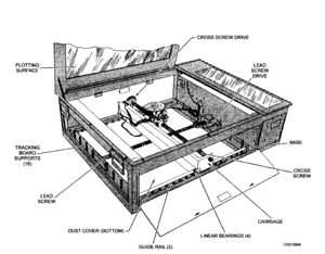
The NC-2 plotter was a desk sized device with a glass top and a mechanically driven projector that shined a polar grid plot up onto the glass. A large sheet of tracing paper was laid over the glass top so that the polar grid layout showed very clearly on the paper in the darkened CIC. Inputs from the ships gyro compass and underwater speed log drove the projector, universally called ‘the bug’ so that the center of the polar coordinate projection replicated the ships path through the water. If you were tracking a submarine contact, you could make periodic sub range and bearing marks on the tracing paper (using a draftsman's pantograph square), as well as periodically marking own ship’s position. The result was a replication of both the sub’s track and own ship’s track. This plot was very useful in prosecuting a submarine attack, and next to the sonar itself, the NC-2 plotter was probably the most useful ASW tool in a surface ship.
Emergence of O/C - Step 1
What we wanted was an electronic digital version of the NC-2 plotter. From my fleet ASW experience, I also wanted it to have an internal memory so that it could recall and display track histories of up to 60 submarine, surface ship and aircraft contacts. These track history displays would also be updated at a faster rate than available from the computer memory. We wanted the display to be as large as possible, and we wanted it nearly horizontal so that a number of people could stand around it and all see the situation. Just as they did with the NC-2 plotter. We wanted the device to have the same auxiliary readouts as the regular NTDS consoles so that an operator could select a particular track and get readout of its course, speed and other amplifying data. The readouts would be along one edge of the console and users would stand around the other three edges.
To allow the maximum number of people to see the scope face, we estimated that the display surface should be tilted down about ten degrees from the horizontal toward the front side of the console. At that time, I was also the manager of an exploratory development program searching for a practical large panel display technology that could be adapted to a warship application. I was already pursuing a form of liquid crystal display that went to sea about 1968 and was eventually installed in amphibious command ships and Aegis Weapon System ships, but there was nothing I knew of that was immediately available in a rugged configuration that could (with high resolution) react in micro seconds. This was 1964 and we had only three years from “go-ahead” to fleet operations. A “solid state” large panel display was still a dream. We knew we would have to settle for a cathode ray tube display, but it had to be as large as possible.
We concluded that a 22” CRT was about as large as we could find that could handle the high speed demands of the wide magnetically-induced beam deflection and the symbol repertoire. Several years prior BUSHIPS had contracted with the Budd Electronics Division to build a prototype 22” display but it did not have the requisite features we wanted and was incompatible with the new AN/ UYA-4 NTDS display subsystem development schedule. We came up with the name Operations Summary Console (O/C) for the new device, and Cdr. Wilde and I presented the concept to Vadm. Martell. He though it was a great idea, and agreed to add it to ASWSC&CS. (We had our fifth console!)
The O/C - Step 2
Our other OPNAV sponsor, Commander Chan Swallow, also thought the O/C was a good idea, but disagreed strongly with the tilt to the face. He thought it should be horizontal like the NC-2 plotter. The tilt was the subject of more friendly lighthearted discussion than it was worth but we asked Hughes Aircraft (the display contractor) to build a wooden mockup of the O/C and ship it to Washington. It was rather large and blocked access to our small office for several days. Once we were able to demonstrate the utility of the tilt Commander Swallow agreed. We later had good reason to doubt our CRT decisions when one of the tubes exploded in a Hughes test shop and blew a hole in the ceiling where the CRT gun departed. Luckily, it was on a weekend when no one was in the building. Hughes met with the supplier and fashioned a protective covering for the tube. O/Cs eventually became standard in the fleet and I have never heard of another one exploding.
The Interface Mating Game - Step 1, A to D, and D to A
We faced a fundamental systems incompatibility on the DE, in that they had two large analog systems that we had to interface with, i.e. sonar and Mk 114 underwater fire control system. For our part, we wanted our displays in CIC to show raw radar video as well as computer generated symbols, and for this new application; raw sonar video, meaning a new sonar scan converter analogous to the NTDS radar azimuth converters so that sonar sweep signals were available in the radar switchboard. This may have been one of the more profound moments in the project -- when I went to the sonar groups in the Bureau of Ships and asked for technical data on the imposing SQS 26 sonar.
The Interface Mating Game - Step 2, taking on the Gods of Sound
I was about to challenge the regal autonomy of the navy’s sonar technology czars when I told them why I wanted the information. “We don’t interface with anything.” “You must get your search and detection information by sound-powered telephone from the sonarman after he has pronounced a formal target “classification” - - a la Red October. The idea of tapping off electrical interfaces with the analog giant and displaying a sonar sweep in CIC was heresy. They even denied my request to talk to EDO Corp., the sonar manufacturer. Eventually, however, I was accorded permission to talk to the EDO Systems Division which was not directly involved in the SQS-26 program. The meetings with EDO and Hughes Aircraft were productive but (at times) amusing with two cultures finding their ways in the other’s - - analog vs digital; wideband meaning 3 kilo hertz vs 10 mega hertz; synchro-driven readout dials vs alpa numeric digital readouts; etc. I had to walk quietly in the hallways of the Old Main Navy Building where the God’s of Sound reigned.
The Interface Mating Game - STEP 3, The Little Gray Box
The little gray box was called the Target Entry Unit (TEU). It was a very simple device that provided a means whereby operators on the analog systems could alert the digital computer input/output facilities that timed target information was available for its use in the fire control switchboard. The form of such signals was generally synchro voltages. They were connected to the computer via the NTDS keyset central multiplexer (KCMX) and the switchboard. For example, the sonarman, while tracking a contact, could enter target location information into the ASWSC&CS by putting his display “bug” over the target and pressing the large “Enter” button on the TEU - -thus attaching a precise time tag to the target position. My experience suggested that time was a poorly managed variable that causes track registration errors around a task force. I wanted ASWSC&CS to solve this mundane problem. The TEU also solved my problem of imposing additional duties upon the sonarman (who resides in the Gods of Sound safe house and confronting the Gods themselves).
The TEU concept was pretty much my idea and there were three or four different versions. I wanted them to be as simple as possible so no operator could be distracted from his primary duty. The “KISS” (keep it simple stupid) direction was sometimes hard to enforce. Our first cut started with me telling Navy Electronics Laboratory engineers to “come here next week with a functional design of a sonar TEU. They rolled out a drawing of a box with a maze of buttons and readouts. By the end of the day we were down to three or four buttons including an on/off and enter buttons.
Get the Captain off the Bridge
Although I cannot remember if the SOR established the goal, I was intent upon “getting the captain off the bridge” during submarine engagements. This refers to the habit of ASW ships’ captains to stay on the bridge while directing anti-submarine engagements. They used sound-powered telephone earphones to gather submarine positions and maneuvers from the sonarman, or the CIC Officer operating the NC-2 plotter, listen to the sonar returns on a bridge speaker, and direct weapons deployment. The practice was popular because the antiquated WW II era facilities in CIC offered little advantage over that available on the bridge and the captain had a better feel for the ship handling dynamics of the engagement - - from detection to weapons launch. ASWSC&CS was successful in that goal because it offered the tools to display and progress the engagement with a greatly enhanced clarity.
I wanted our ships to be able to assess the ship/sub tactical situation on a ping-to-ping basis. Submarines have many ways to use water to their advantage. They can hide behind temperature gradients/layers, and confuse the surface ship with such things as sound decoys, rudder “knuckles” and bubble masks that will send the attacking ship on a wild goose chase in the wrong direction. While cloaked behind such distractions, the sub can quickly dive below the inversion layer and be lost forever. The precise handling of target historical data and a sonar sweep overlaid with track symbols was intended to keep the captain from turning the ship in the wrong direction or attacking a sound decoy. We also developed a specialized ASW Keyset for installation in the CIC. The intent was to enabled the CIC crew to quickly enter stylized detection, engagement, contact classification, tracking, etc. information for broadcast on Link 11 and integration with the task force tactical picture.
I was particularly enamored with the idea of putting a sonar sweep in CIC. The sonar people said there was no way I was going to hook into the time- frequency capabilities and displays of the passive mode of the sonar. They said I could only tap into the rotating scan display which was intended primarily for active sonar operations. That was fine for me, because it gave us an improved capability to attack submarines, while the sonar purists pursued their listening operations. Our ASWSC&CS target tracking capabilities in the listening search mode were quite modest and evolved at a slower pace, but the tracking data rate from the passive sonar was also developed at a slower pace. The time from detection to isolation and engagement could be quite long but, all in all, I anticipated that the insertion of ASWC&CS into the equation would yield a giant step forward in target tracking and isolation - -leading to a productive engagement.
Buying the Display Hardware
The NTDS AN/SYA-4 display subsystem was in current production, by Hughes Aircraft but it did not have all the features necessary to support ASW. In addition to the new requirements for the operations summary console and sonar scan converter, the SYA-4 subsystem would have to be upgraded with a number of new ASW related computer generated symbols, and I wanted also to include numbers in the new symbology. Others in the NTDS project office wanted to be able to write alphabetic messages on the console faces, and still others wanted the scopes to be able to show television images. It became apparent that making all these modifications to the existing SYA-4 subsystem would probably be about as expensive a developing a new NTDS display subsystem; and furthermore advances in technology pushed thinking toward developing a next generation NTDS display subsystem. Vadm. Martell agreed that he would sponsor a complete new generation display subsystem. He would pay for enough new research and development equipment to equip the three test ships (plus a shore test and training set), and if the equipment passed operational evaluation, and was service approved, it would become the new generation of standard production NTDS displays.
A little know fact was that the first UYA-4 competitive production contract was awarded in mid 1965, a few days before the UYA-4 ASWSC&CS sole source negotiated development contract. We had to work fast to baseline the ASWSC&CS contract and specifications for the four sets of R&D equipment so that production on the other contract could proceed. It’s amazing how much you can get done if no one is looking and your leaders are in a hurry.
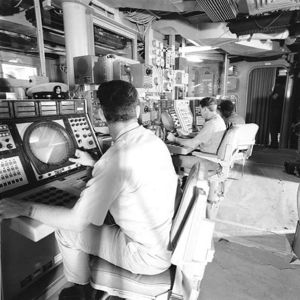
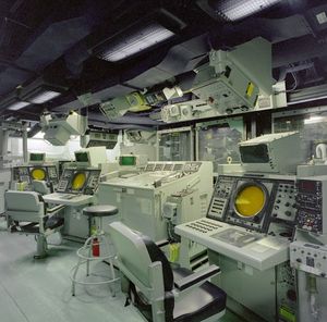
We got the Navy nomenclature AN/UYA-4 assigned to the new subsystem, and Mr. Frederick A. Russell in the BUSHIPS Radar Branch became the Project engineer. Thus time the team of Russell and Hughes Aircraft were able to merge the NTDS user and data input consoles into one 12-inch PPI universal console. The other two console types would be a radar height/size analysis console, and the new operations summary console. The new technology of microelectronics circuitry allowed shrinking the volume of console electronics so that the auxiliary readout indicators could be built into the console, and the separate stand-alone auxiliary readout cabinets eliminated. The new generation of consoles was now intended to support an expanding number of warfare areas so the number of console use settings, whereby the console operator told the computer what his/her console was being used for, was increased from the number of SYA-4 settings. The new UYA-4 sensor distribution switchboard could connect the new subsystem to 11 different sensors at a time; including radars and sonars.
Buying the HF Radio (Link 11) Hardware
Lieutenant Commander George A. Friese of the NTDS project office was concurrently at work developing the next generation of tactical data link (Link 11) equipment, and the timing was such that the ASWSC&CS ships would be the first to use it. As such, the ASWSC&CS project was also paying for the new Link 11 equipment development. I had always thought that the AN/SRC-16 brute force 5,000 watt Link 11 transmitter was overkill (to achieve 300 mile ground wave gapless coverage) and could be substantially reduced in power. George and I did some back-of-an envelope calculations that showed that the (physically) large 5,000 watt transmitter could be reduced to 1,000 watts with the planned installation of a new automatic antenna coupler and an improved shipboard wide band wire antenna that rendered the whole forward part of the ship an antenna. I got the funding for George to develop the new antenna coupler and antenna design. At-sea testing during ASWSC&CS evaluation would prove our quickie calculations correct.
Buying the Memory Disk File RD-281 Hardware
Anti-air battles move very fast, and are generally over in a short time, whereas an anti-sub engagement can last for days and necessitate a lot of record keeping. In addition to the track history storage in the operations summary console, I could see the need for additional mass memory storage to support anti-sub operations. The NTDS project was also developing a rotating mass memory storage device, mainly for at-sea logistics operations, intelligence data storage, and amphibious command operations. But I thought it would be very useful to also have the new IBM RD-281 military hardened rotating disk file as part of the larger Wasp’s ASWSC&CS system to automatically store detection, engagement, and track histories over a wide geographic area covering a period of days for later analysis and correlation.
Bringing on System and Software Contractor
By mid 1965 we were bringing on our systems, integration. and software contractor - Univac. They would draw upon their San Diego and Saint Paul engineering pool to man the work. We set up their team in a large old barracks building on the Navy Electronics Lab grounds to save money. They would also assist NEL in setting up the shore test site, training Boston Naval Shipyard employees on the installation and testing of computer based digital systems, and the program generation facility.
Raymond J. Kott was the Univac Program Manager Gordon A. Erickson was the software Manager
Commander Bill Potter was the NEL Program Manager Mister Paul Ward was the NEL Assistant Program Manager
About 90 percent of the NTDS equipment planned to go aboard the three ASWC&CS ships was ‘next generation’ equipment that would see first time use in these ships. This included the new keyset central multiplexer that featured an expanded number of synchro signal inputs (32) over the eight in the original NTDS keyset central. Among other things, this gave us the capability to bring precise range and bearing measurements from gun and missile fire control radars, as well as sub positions from the underwater battery fire control computer, into the NTDS computer. This opened the opportunity to add software to use the NTDS computer to facilitate what is called a “Deep Creep Attack,” whereby, a “non-pinging” attack ship can move in on a submarine, its gun fire control radar locked on a remote “pinging” assist ship, and offset the tracking equations so as to launch a surprise attack on the unsuspecting submarine using the pinging ship’s tracking data. I suspect this process might have been used a number of times, given the number of reports of soviet submarines surfacing and being surprised to find a silent ASWSC&CS ship in close proximity.
Boston Naval Shipyard was not only tasked to install ASWSC&CS equipment in Wasp, Voge and Koelsch, but later the yard was scheduled to install NTDS in the heavy missile cruiser Albany. The Yard had never before done an NTDS installation so we worked out a plan to send Lt. Walter X. MacDonald, the yard’s assistant combat systems superintendent, and Mr. Harry Ampagoomian of the Design Division, accompanied by a few design engineers and installation specialists, to work for a number of months at the NEL engineering test site to gain practical experience. We really lucked out with Walt and Harry. I got Walt by going to the Bureau of Naval Personnel with a request for a high performance officer to guide the ship work through the inexperienced shipyard. He was an ex 20-year plus veteran Chief Petty Officer in three technical ratings and a Purdue engineering degree with honors. I called him my secret weapon to whom you dare not say a building is in the wrong place because you might find an empty lot the next morning.
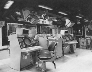
Young Harry guided the yard design work so expertly that he was offered a job in the BuShips design division in Washington. He took the job and worked on many ship building programs until his retirement years later. When they returned, MacDonald and Ampagoomian would be in charge of the ASWSC&CS and NTDS installations. One of Ampagoomian’s first tasks upon returning to Boston was finalizing the equipment layout design in the three test ships in accordance with a “work-study” document produced in our office with the help of a support contractor named The Stanwick Corp. The DE’s design put the O/C in the center of the CIC, where the NC-2 plotter would normally have gone, with the four UYA-4 PPI consoles arranged in a U formation around the O/C. The NC-2 plotter was placed in a remote corner. Some ASW specialists were not happy the arrangement.
Meet the Crew
As system design progressed, I traveled to Bay City, Michigan with Paul Ward to see the ships and interface with the prospective crews and invite the Prospective Commanding Officers (PCO) to review and advise us on system functions and design. Commander John A. Buck, PCO of Koelsch, Commander William F. Keller, Voge’s PCO, and the ASW Carrier Division’s chief of staff, Captain Taylor, took us up on the invitation. Cdr. Buck, in particular, was very upset with the CIC arrangement, especially the location of the NC-2 plotter. In his way of thinking the NC-2 belonged at the center, and he felt so strongly that he traveled to Washington, D.C. to object in person to the sponsors in OPNAV. In spite of all my reasons and rationale as to why he was not going to need the NC-2, he was not convinced.
Shipyard Installation
Wasp, Koelsch, and Voge arrived at Boston Naval Shipyard in early 1967, and thanks to the experience gained at the NEL engineering test site, ASWSC&CS installation went without problems. Walt MacDonald enlisted the assistance of a Chief Data Systems Petty Officer from Voge to help him fabricate a dockside test facility where all equipment intended for installation was hooked up and operated “under full load” prior to moving on to the ships. I am sure this was a major factor in the success of the project. One major “glitch” occurred when one of the KCMX’s fell off a fork lift and landed on its top. We had to send it back to St. Paul for repairs, but the yard was able to fashion a workaround plan and maintain the urgent schedule without losing a beat. In January 1968 Wasp finished her overhaul, and Koelsch, and Voge left the yard in February.
Let's Try It Out
The three ships rendezvoused near Guantanamo Bay, Cuba, where they exercised the new system, and the Operational Test and Evaluation Force ran a formal operational evaluation (OPEVAL). The system passed OPEVAL with flying colors; in particular the final report noted that there had been none of the operational computer program problems that plagued the original NTDS operational evaluation. Wasp’s commanding officer noted that the rotating magnetic disk file’s ability to save and present large amounts of track and contact histories was especially useful to the ASW Group Commander.
How Did It Score ?
Koelsch’s CO, Commander John Buck, who had so severely criticized the destroyer escort’s CIC layout, sent a message addressed directly to CNO commending the system’s performance and retracting his complaints. He later reported that in Koelsch’s first operational readiness inspection the ship ran up the highest ever achieved ASW score. For a number of years the three ASWSC&CS ships operated together as a hunter/killer group and gained the reputation as the best in the fleet. I kept an ear open for reports of their performance in my new job as Fleet Electronics Officer on the staff of CinC Lant Fleet. Reports were positive.
Commander Buck made a profound observation in his message to CNO. He cited US Navy dogma that said a successful submarine engagement required the efforts of two ships, i.e. one attack ship and one assist ship. He said one ASWSC&CS ship could do the job.
Building a Fleet Reputation
Voge, in particular, went on to have an exciting career. In June 1969 in mid Atlantic, she detected a submerged submarine, later confirmed as a Soviet Yankee Class ballistic missile sub. Voge used hold-down tactics on the Soviet sub to the point that she forced the sub to surface. For this action the DE was awarded the Meritorious Unit Commendation. In another demonstration of her capability in early November 1972, Voge was assigned to shadow Soviet submarines reporting to and leaving the Mediterranean. One time, she tracked a departing Soviet submarine 300 miles out into the Atlantic before voluntarily breaking off contact and going back to the Mediterranean. The soviets didn’t like being tracked and pinged upon for hours on end and did their best to break off contact.
On 28 August 1976, Voge was in company with USS Moinester (FF-1097) in the Ionian Sea off Crete, when she saw the periscope of a Soviet ECHO class guided-missile sub, later identified as the K-22, apparently shadowing Moinester, and apparently unaware of Voge’s presence. For about two hours Voge’s crew kept K-22 under surveillance, even to the point of getting a number of photos of the periscope. K-22’s skipper apparently lost track of Moinester a number of times, and appeared to loose her completely at about 1815. At about 1825, the sub skipper noticed Voge for the first time and realized he was about to collide with her. Too late he ordered an emergency dive, and seconds later K-22’s bow and sail rammed Voge’s port quarter. The impact tore open part of Voge’s hull and caused the after steering room to flood, as well as tearing off part of her single propeller. The shock also caused injury to a sailor who was knocked from the 01 level to the main deck. K-22 stayed afloat, but suffered severe damage to her bow and sail. A Soviet ship showed up to escort the stricken submarine to port. With part of her propeller gone and flooded after-steering, Voge was taken in tow by Moinester, and later by the salvage ship Preserver who towed the DE to Toulon, France, where she had to be dry docked for repairs.
In genera, the two ASWSC&CS equipped destroyer escorts made a science of tracking Soviet subs and started a whole new concept of the ‘hold-down’ exercise. They had the capability to keep on tracking a Soviet sub until either she surfaced or the tracking ship ran out of potatoes. There was even a rumor that an exasperated Soviet sub skipper who could not shake his pursuer surfaced and threatened to ram him if they did not stop pinging on him. The subsequent deployment of the “Towed Array Sonar” substantially increased this ability .
What's Next?
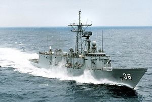
As I previously mentioned, ASWSC&CS was not an end in itself but rather a research and development project to guide the design of combat direction systems for later ASW ship classes. The system formed the basis of the combat direction systems in the 31 ships of the Spruance Class destroyers, the 55 ships of the Oliver Hazard Perry Class of guided missile frigates, as well as other later ship classes.
